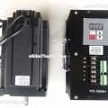
WS-390NH drive uses a dedicated brushless DC motor driver chip, the controller is suitable for driving large and medium-sized brushless DC motor. As a result of the new PWM technology, the motor running speed, small vibration, low noise, stable operation.
Special features
1.1 Power AC working voltage 110VAC-220VAC.
1.2 PWM frequency of not less than 12KHZ.
1.3 drive rated current up to 18A.
1.4 drive rated power 3300W.
1.5 Dimensions: 200 * 105 * 105.
1.6 Weight: 2.01Kg.
1.7 The drive has two functions, running with Hall motor can also be run without Hall motor.
2. Pin Description
2.1 110VAC-220VAC AC input or external DC power supply.
2.2 U-phase motor U phase.
2.3 V terminal for the motor V phase.
2.4 W terminal for the motor W phase.
2.5 +5 V terminal for the Hall element power supply, the driver provides.
2.6 GND The negative terminal of the Hall element power supply, ie 0V.
2.7 HALL A is a phase A Hall element.
2.8 HALL B is a B phase Hall element.
2.9 HALL C is a C-phase Hall element.
2.10 CW end for the positive direction of the motor is enabled, low active.
2.11 CCW terminal for the motor to run the opposite direction enable, low effective.
2.12 BRAKE end for the brake, low effective.
2.13 DA terminal for the motor speed potentiometer, 0V to 5V, can be changed to 0V to 10V.
2.14 Hall port is not connected, running Hall-type motor. See 3.5 Operation Method.
3. Parameter setting
Power on display shows "A --- BB", A = 0 means no Hall motor running, A = 1 means running Hall motor. BB represents brushless motor series.
About 1 second after running speed value.
3.1 Press the SET key for the first time to display "--- BB". BB means the brushless motor stage. Press the up and down keys to select the same number of stages as the brushless motor.
3.2 Press the SET button for the second time to display E x.x, indicating the brushless motor speed-up time.
3.3 Press the SET button for the third time to display L, press the up and down keys to display "0" "1". "0" means open loop. "1" means closed loop.
3.4 Closed loop parameter adjustment: Press SET key: Display "xxxx" means closed loop maximum speed.
Press the SET button: The "P xx" range is displayed from 1 to 99.
Press the SET button: The "I xx" range is displayed from 1 to 60.
Press the SET button: The "d xx" range is displayed from 0 to 10. General closed-loop parameter adjustment P value is greater than I value. Note: L = 0 when shipped.
3.5 Press the key three times in succession to display "H --- X". Press X = 1 to show Hall operation, press key X = 0 to show Hall-free operation.
Press Enter to save the data.Note: When you change the Hall or Hall-free operation, the data needs to be powered off to take effect after the data is saved.
Factory setting: With Hall operation, acceleration time E = 1 second, open loop operation L = 0.
4. Fault display
Drive failure display alarm
4.1 "Err 3" indicates overcurrent.
4.2 "Err 5" indicates stalling overcurrent.
4.3 "Err 6" indicates Hall has a problem or motor U, V, W phase is disconnected.
5. Electrical Characteristics (T j = 25 ℃)
5.1 Power AC voltage 110VAC-220VAC.
5.2 The maximum output current 10A.
5.3 Insulation resistance greater than 500MΩ.
6. Use of the environment and parameters
6.1 cooling method; natural cooling or forced air cooling.
6.2 Use of the environment; try to avoid dust and corrosive gases.
6.3 Temperature; 0 ° C- + 50 ° C.
6.4 Humidity; 40-89% RH.
7. Power supply
7.1 Power AC voltage 110VAC-220VAC.


